The most common such applications are large equipment flanges and heat exchangers body flanges. Non-standard flanges are designed and calculated according to ASME VIII Div1 Appendix 2 and Appendix S and according to ASME VIII Div2 part 416.
2
That type of flange connection cannot be assessed by using ASME VIII Div.
. This was widely used to field fabricate blinds before ASME introduced ASME B1648 and made them a. As th e calculation meods ar limited so standards us real test requirement to ensure compliance for non-standard components. Modulus of elasticity at atmospheric temp.
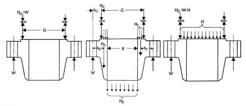
Design criteria Rules for the design of bolted flange connections as described in Div1 Appendix 2 apply to flanges with gaskets placed entirely within the circle enclosed by the bolt holes and with no contact outside this circle. Fabrication and Welding 6. Manufacture and Workmanship 7.
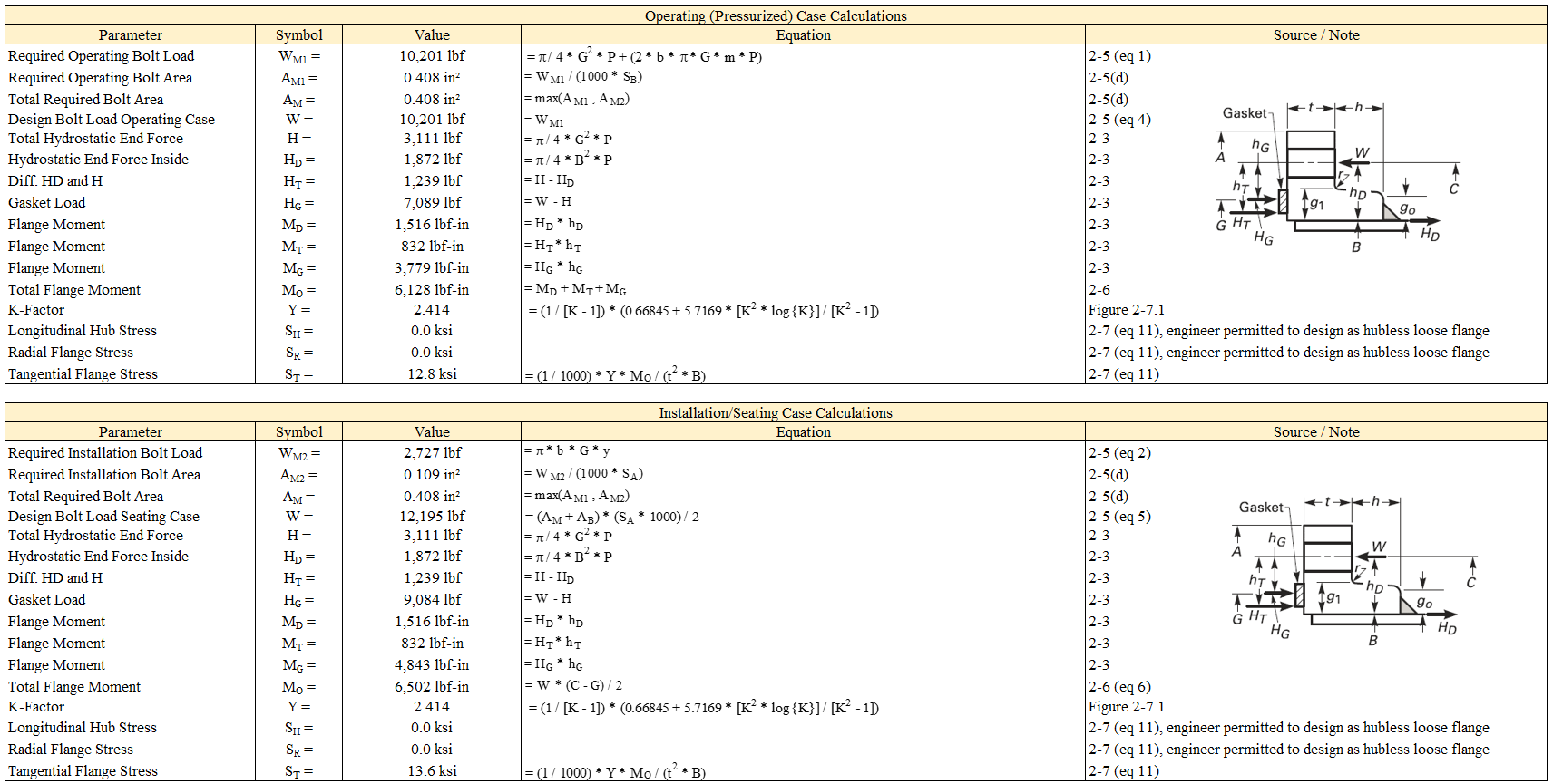
Flange Calculations for Non-Standard Flanges 5. For example based on visual leak evidence or. We have to proceed a design calculations as per ASME code Section VIII Division 1-Mandatory Appendix 2 Rules for Bolted Flange Connections with Ring Type Gaskets about 10 pages of detailed calculations per flange integral loose and optional type and blind flange shall be carried out in accordance with ASME UG-346 6 pages.
To start viewing messages select the forum that you want to visit from the selection below. Click the register link above to proceed. Non-standard flanges are designed and calculated according to ASME VIII Div1 Appendix 2 and Appendix S and according to ASME VIII Div2 part 416.
Non standard flange design calculation In case you are a lover of nail art but are certainly not accustomed to the various coats of acrylic then such a design could possibly just function nicely for you. Non Standard Flange Design Calculation. 16 Bolts x 1 dia on a 2025 BCD C r.
Gasket OD 1775 Gasket ID 1625 Gasket m 3 Gasket y 10000. Design criteria Rules for the design of bolted flange connections as described in Div1 Appendix 2 apply to flanges with gaskets placed entirely within the circle enclosed by the bolt holes and with no contact outside this circle. Non-standard flanges are designed and calculated according to ASME VIII Div1 Appendix 2 and Appendix S and according to ASME VIII Div2 part 416.
For Non-Standard Flanges. Waters method is established on the basis of online elastic plate and shell theory of non-standard flange design calculation method whether it is internal pressure flange or external pressure flange in addition to the flange moment calculation formula is different according to the flange ring and cylinder or including tapered neck connected to the degree. Welding Qualifications Section III.
Wangzh2k you most assuredly can design a non-standard flange with Appendix 2. If this is your first visit be sure to check out the FAQ by clicking the link above. You may have to register before you can post.
Modulus of elasticity at design temp. Allowable stress at atmospheric temp. Foreword Section I.
Further use of Dialog control language boxes enriches the program and provides user friendly environment. Torque calculations are based on the simplified formula explained in the current version of. Inspection Tests Marking and Records.
2 part 416 13 calculations. Inside Diameter B 1600 Outside Diameter A 22 Thickness t 175 Hub radius r 0375 Pipe thickness g0 075. For approximately the last three years ULMA Piping has been learning and incorporating new methods and technologies for the design of non-standard flanges.
The non standard flange design automation program is written in Auto LISP language compatible with AutoCAD Drawing package. Allowable stress at design temp. If you alter any database input value the flange gaskets calculator will recalculate using your modified values.
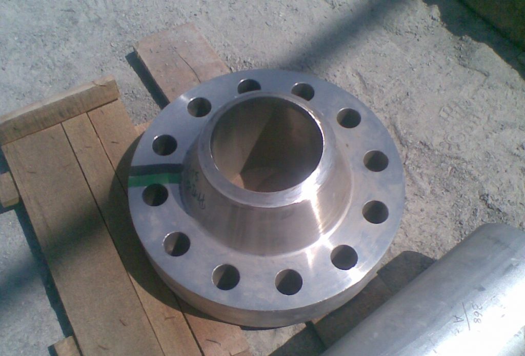
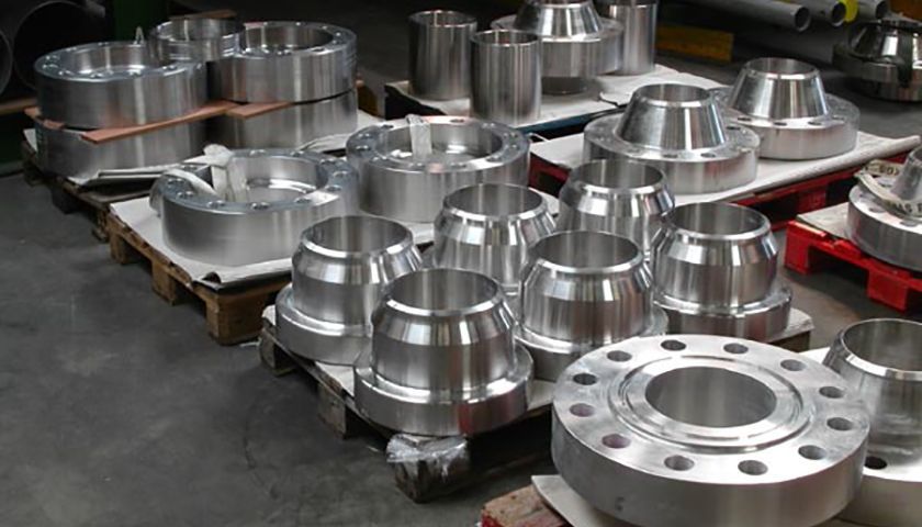
These flanges have special characteristics requiring a specific design process to fit the working. Root diameter d b. If you have access to an old API standard called API 590 it actually contained tables of blind thicknesses based on the calculations in B313.
2 shows flow chart for design Automation of non standard flange. General Materials and Design 1. Internal design pressure P.
As for your ASME no longer ANSI standard flanges while I am not sure of the exact reasons it is well known these do not meet Appendix 2 design. The Flange design and calculation of ULMA Piping certified for by the API and ISO. In this way you may determine a basic gasket seating width for non-standard gaskets.
Non standard ASME Flange Design Calculations Excel sheet for Pressure Vessel. EN 1591 is a comparatively new European Standard which unlike most conven- tional flange design methods eg ASME VIII provides design rules that ensure leak tightness of a BFJ. I believe that at least part of the reason is they are typically much over-bolted compared to Appendix 2 design.
Welcome to this interactive flange bolting calculator from HYTORCThe program computes recommended torque values bolting patterns tool selection and pump pressure settings for standard ASME B165 and API 6A flanges under normal assembly conditions. However when you select an alternative gasket the input data will automatically revert to the database values on your return. Materials of Construction and Allowable Stress Values 3.
Appendix G of this Standard incorporates the comparatively new flange calculation rules provided in European Standard EN 1591-1 2009. Pressure Relieving Devices Section II.
Non Standard Flanges Asme Viii Arveng Training Engineering
Flange Thickness Calculation Sk

Non Standard Flange Calculations Video 2 عربي Youtube
Asme Flange Design Calculation
2

11 How To Design Nonstandard Flanges On Standard Nozzles Autopipe Wiki Autopipe Bentley Communities
Non Standard Flanges Asme Viii Arveng Training Engineering

Non Standard Flange Design And Bolt Tightening Basis Video1 Youtube
0 komentar
Posting Komentar